September 22, 2017
A Hill in the Middle
Originally published March 9, 2008

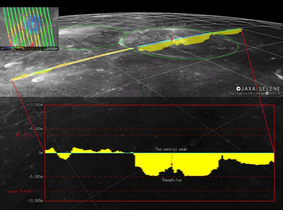
image from JAXA/Selene
The Kaguya science team has released some new images from the HDTV and interesting results from the laser altimeter. The insert at upper left shows the tracks of adjacent altimeter traces and color-coded heights over Theophilus (blue interior). The main image is a profile along the track that crosses near the center of the 100 km wide crater Theophilus. The text accompanying the release states that the north rim is about 2000 m above its surrounding terrain, the crater is 5000 m deep and the central peak is ~2000 m tall. According to the Lunar Topographic Orthophoto map of the northern half of Theophilus, the greatest crater depth is 4818 m and the peak reaches a maximum of 3014 m. The Kaguya crater depth is in excellent agreement, and the difference between the peak heights may mean that the track misses the highest point of the peak. And it appears that the altimeter footprint is about 6 km wide so it determines an average elevation for a swath width, not a point. The vertical cliff on the left/south side of the rim is unlikely to be that steep. Theophilus does have impressive faults scarps high up on its rim, but the steepest slope previously estimated was 46°. It is fitting that some of the first released Kaguya topographic information is of Theophilus for that was the crater whose profile was measured in 1932 at the McMath-Hulbert Observatory in the first innovative use of a movie camera to track sunrise across a crater.
Chuck Wood
Technical Details
A full size image of the small insert of ground tracks is at the Kaguya Image Gallery - click the LALT button.
Related Links
Rükl plate 46
Kaguya/Selene website
Yesterday's LPOD: Not Flying
Tomorrow's LPOD: Lunar Pathfinder Getting Ready
COMMENTS
(1) Chuck,
Satellite LIDAR experiments sample widely spaced, but very small points; so I believe the swath width shown in the illustrations has no physical meaning. The experiments typically send a laser beam to the lunar surface. This illuminates a very small spot and the timing of the flash it produces is determined by monitoring the intensity detected at a single pixel in a high resolution telescopic image. Depending on the telescope, that can mean that the area sampled is even smaller than the already small patch illuminated by the laser.
For example, according to the NSSDC description, the Clementine Laser Altimeter could operate at two wavelengths, one sending out a beam with a divergence of less than 0.5 milliradians, and the other with a divergence of 4 mrad. At a typical observing range of 100 km, 1 mrad of divergence produces a spot on the lunar surface of just 100 km X 0.001 = 100 m. So at one wavelength the spot illuminated on the lunar surface was less than 50 m in diameter, and at the other about 400 m. In both cases, the flash was detected over a 0.057° (1 mrad) wide section of a high resolution image. So in the first case an average over the entire 50 m spot on the Moon was measured, and in the second case, just the center 100 m of the larger spot created by the laser. So the Clementine spots were very small, although a measurement was made at most every 1-2 km.
I'm unable to find as precise of specifications for the Kaguya altimeter, but again according the NSSDC description, the outgoing beam divergence is 3 mrad which, again assuming a 100 km observing altitude, would illuminate a 300 m patch on the surface. All that is mentioned about the detection system is that it employs a diode in the field of a 20-cm Cassegrain telescope. As with Clementine, this may well restrict the sample to something less than the full 300 m laser patch, but the measurement certainly couldn't average over an area larger than that. As mentioned both on the NSSDC and on the Kaguya LALT site, in its normal orbit samples are taken every 1.6 km.
Apollo 15, 16 and 17 also carried a laser altimeter experiment which, according to the NSSDC description, may have had an even smaller sample area and better vertical resolution than either of the later instruments (?), but was capable of obtaining samples only once every 20 seconds or so (compared to once every second on Kaguya).
The problem with all LIDAR experiments is that despite the excellent results they provide for the isolated points that are measured, there are vast stretches between the points where no information at all is obtained. Even after months of data collection, there will be gaps of 2 km or so between the Kaguya points. Hence the chance of precisely hitting any specific point of interest (such as the highest point on a central peak) is extremely small. In this regard, the Earth-based radar interferometric results from Goldstone are much better since they provide true averages over fixed-size contiguous resolution elements. Presumably the Kaguya team, as did Apollo, will use the altimetry data as a reality check on their stereo mapping efforts (I believe they collect such data simultaneously), which will be necessary to fill in the gaps and produce something comparable to the Earth-based radar maps.
As you note, the present press release illustrates this problem. Judging from the Clementine overlay, what is labeled as "the central peak" of Theophilus would appear to be a somewhat random sample point falling somewhere on what was called Theophilus Alpha in Map B5 of the System of Lunar Craters. Although this is one of the central peaks, Earth-based observations suggest that one of the more northern peaks (called Phi on that map, and also the one shown on the LTO cited in today's LPOD) is taller -- but no samples were obtained there.
As to the slopes shown at the north and south rims, the Kaguya inset diagram appears to show missing data points at these locations. I don't know if this means the data is actually missing or if the results were considered too unreliable to plot: it is evident that most of the gaps come where the spacecraft was flying over the steep parts of the crater wall. This is less clear from the bar chart (where each bar appears to represent a sample point and some sort of interpolation process may have been used), but the inset suggests that 1 or 2 data points were missed at the north rim and 2 or 3 at the south rim. Given the 1.6 km spacing between points, this means that the closest samples plotted, which show a drop of about 2 km in the north and 2.5 km in the south, are separated horizontally by 3.2 to 6.4 km. This gives slopes in the range of 20-30°, but the true slope could be much greater since the true distance over which the drop occurs was not determined.
The sharp drop in the bar chart would probably be more understandable if the results were presented as dots showing the measured heights (vertically) and the sample position (horizontally). The actual surface profile is not the odd digital steps implied by the bar chart, but rather some kind of curve drawn through the measured points. However, landforms being as they are, one is never quite sure how to draw the line between any two points -- it is not necessarily a straight line.
-  JimMosher
(2) I recently reported a problem when attempting to click on the LPOD Index. I would get an error message, my browser would close, and I would be knocked offline. According to Microsoft, the problem is with my AT&T Yahoo browser. The "fix" apparently is to download an updated version of the browser. There is nothing wrong with the LPOD link
Always something with computers. What I don't understand is how I've been able to access the LPOD Index before without any problems, and then suddenly there is a problem and things don't work right. (??) A mystery.
--Bill
COMMENTS?
Register, Log in, and join in the comments.


